

Recording and Processing
This section should be read through completely before implementing. After reading this section, it would be a good idea to review the section on Processing and the section on Exposure Calculation Techniques before implementing this section.
Now that you have your single-beam transmission arrangement set up, you are ready to make your first hologram and measure its density. Each bullet listed is a step in the recording and processing procedure and should be followed in the sequence listed.
The Recording and Exposure
- Turn off your air conditioning or heating systems. This needs to be done at least 30 minutes before you make your first exposure.
- Turn on the laser and let it warm up for 30 minutes if it is not already on.
- Turn on your safelights.
- Practice inserting and removing one or two sandwiched 4 inch x 5 inch x 1/16 inch thick glass plate(s) in the plate holder under safelight conditions depending on whether you're going to use a plate or film.
- Make a simple shutter using a piece of black mounting board whose size is about
4 inches wide and about 12 inches tall.
- Recheck that your plate holder and object scene are properly illuminated. Components can settle over time and throw the illumination slightly off. Put the white card in the plate holder during this recheck. Do this check with the room lights off.
- Remove the white card from the plate holder and using your VOM and solar cell, with the room lights off, take a voltage reading at the plate holder as described in the section Exposure Calculation Techniques and write that voltage down.
- You're now ready to make your exposure. Turn on the room lights. Put the shutter in place, blocking the laser beam.
- Set out the PFG-01 plate box (or film box if you're using film) on a table surface underneath one of the safelights. The safelight should be at least 6 feet away from the location of the plate box.
- Put on a new pair surgical gloves.
- Turn off the room lights so only the safelights are on.
- Remove a recording plate from its box and insert the plate into the plate holder.
During the washing phase of the development process, you can determine the emulsion side of the plate. Lift the plate out of the washing tray water. The water will flow off the plate slower on the emulsion side than on the glass side. We assumed that the emulsion was on the left side of the plate as it sat in the plate box and you've kept this side up while processing. If the up side shows the slower water flow, then our assumption was correct. You can now place an arrow on the outside of the plate box facing to the left with a black marker. If our assumption was incorrect, then the arrow should face to the right. You will find that all the plates' emulsions will face in the same direction inside the plate box.
- After the plate is in the plate holder, go back to the plate box and make sure the box lid is back in placed and locked into the closed position.
- You're now going to leave the room for 15 minutes while the whole recording system settles down.
- Make sure you have a watch that has a second hand so you can make the exposure for the appropriate time.
- After 15 minutes, you can re-enter the room, opening the door slowly and gingerly, and closing the door softly.
- Walk gingerly over to where the shutter is located making sure you don't touch the optical table as you do so. Stand there for 2 minutes. Try not to breathe heavily towards the table and don't shift your footing. Changing your standing position will send vibrations to the table.
- After 2 minutes, tilt the shutter away from the laser and gently lift the shutter off the table keeping the laser beam blocked. Wait in this position for 60 seconds.
- Now lift the shutter out of the beam and make the exposure for 20 seconds. Do not touch the optical table during the exposure and try not to breathe heavily towards the table or components.
- After 20 seconds, block the beam with the shutter without touching the table, and then set the shutter on the table and lean it against the laser making sure it will stay in place. You're exposure is complete.
- Remove the plate from the plate holder remembering that the emulsion, assumingly, is facing the object scene.
- Place the plate in a light proof black box with the emulsion up to prevent possible scratches. These light proof black boxes can be purchased from professional photo stores.
- Recheck that your plate box and light proof black box with the exposed plate are closed and light proof.
- You can now turn the room lights on.
Processing
- Set up four 5 inch x 7 inch processing trays for the developer, stop bath, bleach, and photoflo. The table you process on should have a surface that is not porous and can be wiped down with a sponge. It's inevitable that you will spill some solutions on the table when agitating and transferring the plate between trays. If you want, you could place each tray in their own larger aluminum basting pan to catch spills.
- I highly recommend an apron or lab coat during processing. The developer will stain your clothing and is not removable. Wear old clothing.
- Mix 6 ounces (177 ml) of Pyrochrome Part A developer with 6 ounces (177 ml) of sodium carbonate Part B developer in your one liter plastic graduate measuring cup. Pour Part A into the graduate first, then add Part B. Stir. Pour the solution into the processing tray labeled Developer. Rinse the cup and stirrer in hot water thoroughly and place on paper towel to drain and dry.
- Pour 10 ounces (296 ml) of the stop bath solution into its tray labeled Stop using the measuring cup. Rinse the cup thoroughly before using it in the next two steps.
- Pour 10 ounces (296 ml) of the bleach solution into its tray labeled Bleach using the measuring cup.
- Pour 10 ounces (296 ml) of the photoflo solution into its tray labeled Photoflo using the measuring cup.
- Get your light proof box containing the exposed plate and bring it into the area where you are processing. Place the box away from the area you are processing so solutions don't splash on to the box.
- Turn off the room lights. Make sure the safelights are still on and you're still wearing gloves and other protective items.
- Remove the exposed plate from its black box and lower it into the developer tray gently, keeping the emulsion side up.
- When the 5 minutes is up, pull the plate out of the developer, let it drain into the developer tray until it's just dropping a few drops of solution, then place the plate into the stop bath gently, emulsion up, and continue the agitation technique for 2 minutes. You can now turn on the room lights.
- Follow the processing procedure all the way through the stop bath and wash, but no further. While washing, check for white residue and remove if present. With fresh stop bath, the white residue is usually not present.
- After the wash, soak the plate in Photoflo for 2 minutes with the emulsion up and then air dry the plate for 4 hours at around room temperature (70° F) [21° C].
Density Check
- With the plate completely dry, use the exposure calculation technique to check the plate density. If the plate density is within the range, I want you to go ahead and finish the processing procedure. To do this, soak the plate in running tap water for about 30 seconds at around 70° F (21° C), allowing the emulsion to become saturated with water.
- Now move to the bleaching solution and continue the processing procedure through the bleach, tap water rinse (check for white residue), Photoflo, and finally air drying. Allow the plate to dry for 4 hours with the emulsion side of the plate facing outward.
Viewing Your First Hologram
You are now ready to view your first hologram. Take a piece of black mounting board and place it in front of the object scene facing the plate holder so you can't see the object scene from the plate holder's perspective. Remove the shutter. Since you now know what side of the plate the emulsion is on, hold the plate behind the plate holder in the reference beam with the side of the plate that faced the object scene during the exposure. If you see the image of your object scene as shown in Figure 18a, you can now place the plate in its holder and view it for hours. If you don't see an image, you need to rotate the plate 180 degrees around it's normal to see the image. If you still don't see an image, you may have misjudged which side of the plate was facing the object scene. Rotate the plate 180 degrees around its vertical axis and look for the image again. If it's still not there, rotate the plate 180 degrees around it's normal and see if the image is there. If it's still not there, then vibrations and/or movement occurred during the exposure and you'll need to try again. But with this setup, I'm 99.99% confident you'll have an image.
Figure 18a shows an illustration of what you should see (your object scene will probably be different than the one shown in the illustration). The image in Figure 18a is located in the same position as the original object scene. This image is called a virtual image (like the image you see of yourself in a mirror).
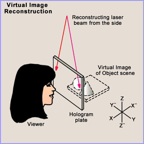
Figure 18a: Transmission hologram virtual image.
Now take the hologram out of the plate holder and rotate it 180 degrees about the Z axis (vertical axis) so that axes X and X- and Y and Y- switch positions. Figure 18b below shows what the image will look like now. You will see the image floating in space between the plate and yourself. This is called a real image because it is actually being focused into space and can be seen on a screen. Using a piece of white mounting board as a screen, you can focus different parts of the image on the card by moving the card through the 3D image.
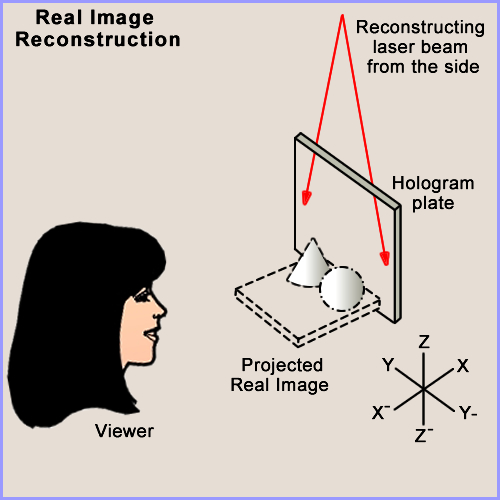
Figure 18b: Projected transmission hologram real image.
You may notice something unusual about this real image while viewing it floating in space between you and the plate. If you move left to right to view parallax in the image, the image moves with you and its parallax cannot be observed. Also, the foreground of the original image has become the background and the background has become the foreground. Left and right parts of the original image have also switched positions. This type of image is called a pseudoscopic real image and is the inverse image of the original scene and the virtual holographic image.
You will use this real image to produce a multi-beam white light reflection display hologram in which the image will revert back to its normal orientation (called orthoscopic). You will also notice that the pseudoscopic real image is greatly magnified. This magnification is caused by the fact that you used a diverging beam during this recording. When you produce a multi-beam hologram, you will use a collimated (parallel) reference beam which will keep the virtual and real images at a 1:1 (1 to 1) magnification.
Transmission holograms have to be reconstructed with laser light. If you tried to reconstruct the image with the sun or a 100 watt clear envelope light bulb, your image would be a rainbow of colors and blurry. Transmission holograms take the full spectrum of the sun or light bulb and creates an image for every color in the visual spectrum therefore creating overlapping images that produce a rainbow blur.
Home | Introduction | Overview | Optical Table | Environment | Laser | Beamsplitter |
Mirrors ⁄ Lenses | Table Mounts | Optic Mounts | Plate Holder | Objects ⁄ Scenes | Hard Copy | Resources
Home | Introduction | Vibrations | Processing | SB Transmission | Exposure |
Recording | SB Reflection | MB Transmission | MB Reflection | Lighting | Hardcopy | Resources