

Beamsplitter
Single-beam hologram optical setups do not require a beamsplitter, but multi-beam setups do and are a critical optical component of the system. A beamsplitter has three important functions:
- To split the beam from the laser into two beams (reference and object beams)
- To control the individual intensities of each of the two beams
- To set the initial directions for each of the two beams
There exists an important intensity relationship between the reference (R) and object (O) beams at the photographic plate in a multi-beam setup. This is called the beam intensity ratio (R/O). The intensity of the reference beam must always be greater than the intensity of any reflected point from the object scene to the plate. Just before you make a multi-beam hologram exposure in the section on Creating Transmission Holograms & Reflection Display Holograms, you will need to adjust the beam intensities of the reference and object beams. The ability to adjust the intensity between the two beams, without changing the directions of the reflected and transmitted beams from their original preset directions, is easily achieved using a variable beamsplitter. I will cover this ratio adjustment in more detail later when you set up for your first multi-beam transmission hologram.
Linear-gradient Variable Beamsplitter
You should try to use a variable beamsplitter. Most are priced reasonably and will make your experience creating multi-beam holograms easier. The least expensive variable beamsplitter you can use is a linear-gradient variable beamsplitter shown in Figure 4a.
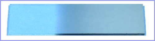
Figure 4a: Linear-gradient variable beamsplitter.
This beamsplitter allows you to slide the beamsplitter through the beam and change the intensities of the two beams while maintaining the preset directions of the reflected and transmitted beams as the intensities are adjusted. This beamsplitter can be mounted a couple ways:
- You can use the optic mount shown in Figure 4b. Building this optic mount is covered under Optic Mounts. The optic mount with the beamsplitter is attached to a table mount and you adjust the beam ratios by sliding the table mount carefully on the optical table surface.
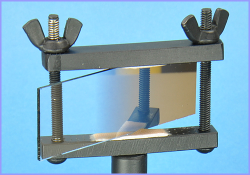
Figure 4b: Optic mount for linear-gradient variable beamsplitter.
- If you need more precise movement when using this mounting method to adjust the beam ratios, you can use a single axis translation stage like the one shown in Figure 4c. You can smoothly turn the knob and move the beamsplitter in small increments along the rack and pinion track.
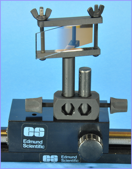
Figure 4c: Translation stage.
- Alternatively, you can mount this beamsplitter in a special mount available from Edmund Optics shown in Figure 4d.
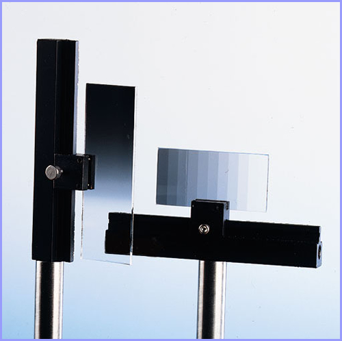
Figure 4d: Adjustable linear beamsplitter mount.
(photo courtesy of Edmund Optics)
- This beamsplitter mount allows more precise movement by using two set screws, which when loosened, allows you to slide the beamsplitter mount along a smooth groove and then re-tighten the set screws.
Circular-gradient Variable Beamsplitter
The best type of beamsplitter, and the easiest to use, is called a circular-gradient variable beamsplitter shown in Figure 4e. A circular-gradient variable beamsplitter has a wheel with an aluminum reflectivity gradient on one side of the wheel to control the amount of laser light reflected and transmitted (the laser beam should impinge on the gradient side of the beamsplitter). As the wheel is rotated from 0 to 360 degrees, the intensity of the reflected beam is decreased while the intensity of the transmitted beam is increased. You can choose either the reflected beam or the transmitted beam as the reference (R) beam. The other beam will then become the object (O) beam. Referring again to Figures 1a and 1b, the transmitted beam (R) is the reference beam in that basic setup.
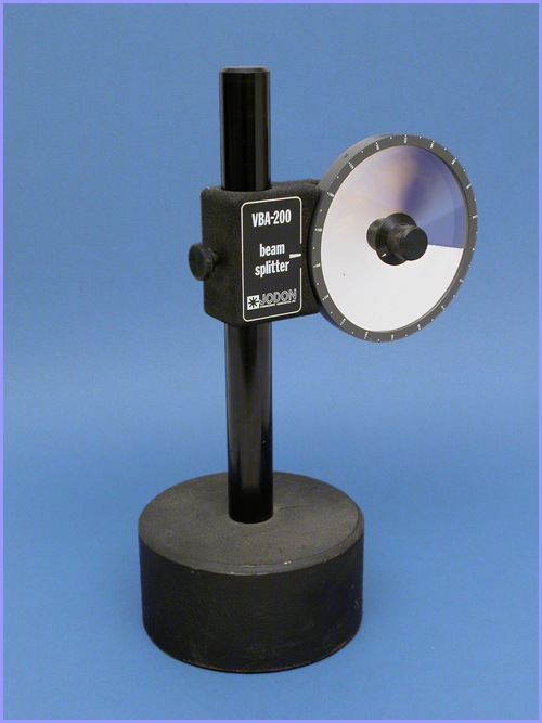
Figure 4e: Circular-gradient variable beamsplitter.
Other Types of Beamsplitters
There are many other types of beamsplitters such as plate, cube, prism, and pellicle beamsplitters just to mention a few. Of the four mentioned, the plate beamsplitters have set ratios of reflection and transmission. This means that if you want to change the ratio, you need to insert a different plate beamsplitter with that ratio. This requires you to have several of these plate beamsplitters, each with different ratios. Additionally, you are limited to how precisely you can adjust your beam ratio because of the limited number of different ratios available.
The remaining three types mentioned only allow you to change the ratio by changing the incident angle of the beam. This in turn changes both the reflected and transmitted beams' directions causing you to realign components downstream of the beamsplitter. I don't recommend you using any of these four beamsplitters. I just wanted you to know about them.
Home | Introduction | Overview | Optical Table | Environment | Laser | Beamsplitter |
Mirrors ⁄ Lenses | Table Mounts | Optic Mounts | Plate Holder | Objects ⁄ Scenes | Hard Copy | Resources
Home | Introduction | Vibrations | Processing | SB Transmission | Exposure |
Recording | SB Reflection | MB Transmission | MB Reflection | Lighting | Hardcopy | Resources